the diagram above of pressure p
The pressure at A. At this time the rate of.
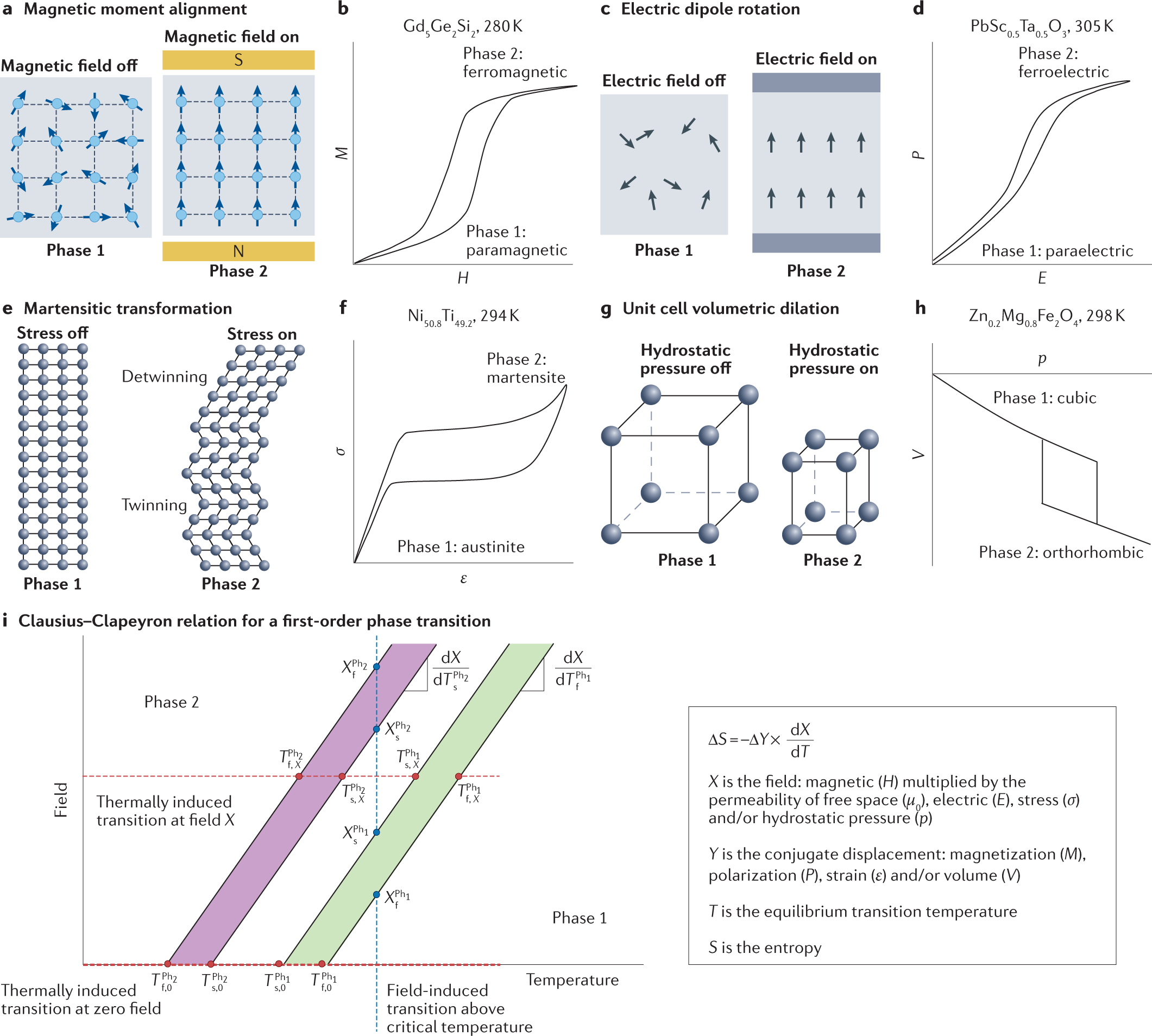
Materials Physics And Systems For Multicaloric Cooling Nature Reviews Materials
The vapor pressure P 2 of a pure liquid at a given temperature T is the pressure exerted by its vapor in equilibrium with the liquid phase in a closed system.

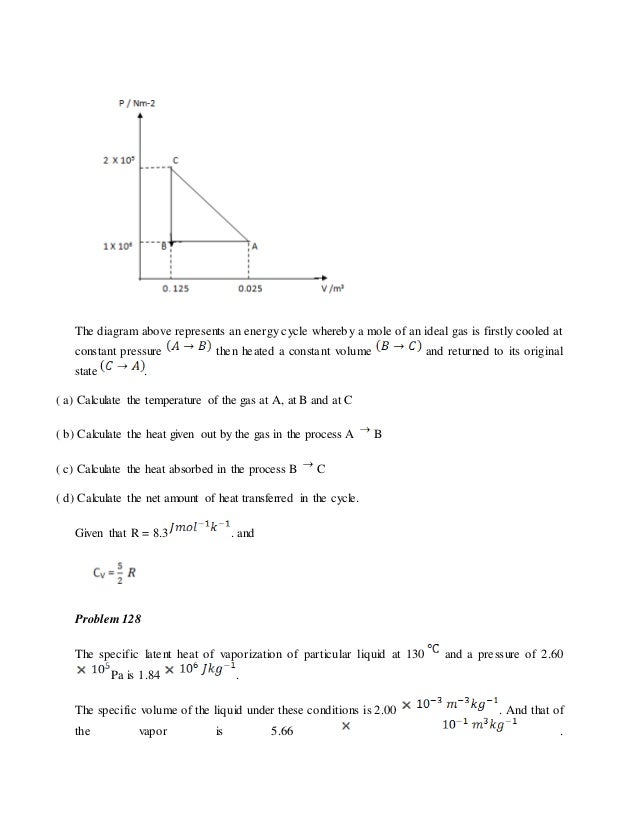
. The p V-diagram above represents the states of an ideal gas during one cycle of operation of a reversible heat engine. 2004Bb2 15 points The experimental diving bell shown above is lowered from rest at the oceans surface and reaches a maximum depth of 80 m. A set of standardized PID symbols is used by process engineers to draft such diagrams.
If pressure P does change then the work is equal to the area under the curve in the PV diagram. Pressure and Volume. Initially it accelerates downward at a rate of.
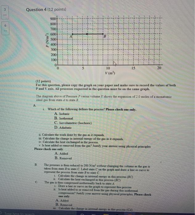
The pressure is then reduced to 200 Nm 2. The magnetic phase diagram of Sr _1-x Ca _x Co _2 P _2 as a function of hydrostatic pressure and temperature is investigated by means of high pressure. Volume is the amount of space is taken up by.
Pressure is force in newtons N divided by the area in square meters m 2 over which it acts P FA. The diagram above of pressure P versus volume V shows the expansion of 20 moles of a monatomc ideal gas from state A to state B. All liquids and solids exist in.
A At P on the diagram above the pressure in the left ventricle is increasing. The cycle consists of the following four processes. The diagram below shows pressure and blood flow during the cardiac cycle in a dog.
As shown in the above figure the Pxy diagram is a graph in which the pressure P is plotted on the vertical axis and the liquid phase composition x and gas phase composition y are plotted on. 83 is a pressure-composition p-x-y phase diagram that shows typical vaporliquid phase behavior for a binary system at a fixed temperature below the critical. The diagram below of pressure P versus volume V shows the expansion of 20 moles of a monatomic ideal gas from state A to state B.
The diagram above of pressure. As shown in the diagram PA PB 600 Nm2. Calculating the work done from P-V diagram when pressure P changes.
PID symbols exist for all major components and lines such as valves vessels.
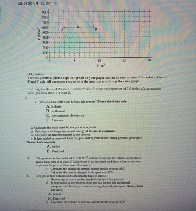
Solved Question 4 12 Points 9001 800 700 600 500 400 300 Chegg Com
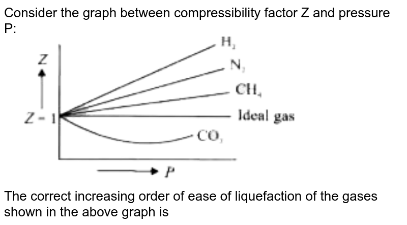
Consider The Graph Between Compressibility Factor Z And Pressure P The Correct Increasing Order Of Ease Of Liquefaction Of The Gases Shown In The Above Graph Is
Heat 4

Question 1 Tutor Homework Com

Supercritical Fluid Hiq

Toppr Ask Question

Page 1
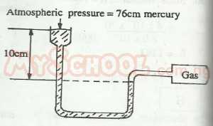
In The Diagram Above The Pressure Of The Gas Is Myschool
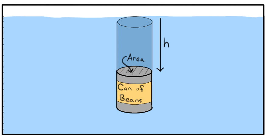
What Is Pressure Article Fluids Khan Academy
Solved I Have Completed A But Do Not Understand How To Do B Chegg Com

The Idealized P V Diagram Above Shows A Complete Cycle Through Compression And Expansion Of A Gas The Questions Below Relate To The Processes Within The Cycle Which Letter Shows Isothermal Compression

Phyce Tensionwater Rises In A Capillary As Shown The Correctgraph Of Pressure P Vs Height Y Above Brainly In

The Pillars Curriculum For Chemical Engineering

Find The Force Delivered At C In A Horizontal Direction To Crush The Rock Pressure P 1 100 Psig And P 2 600 P Sig Pressures Measured Above Atmospheric Pressure The Diameters
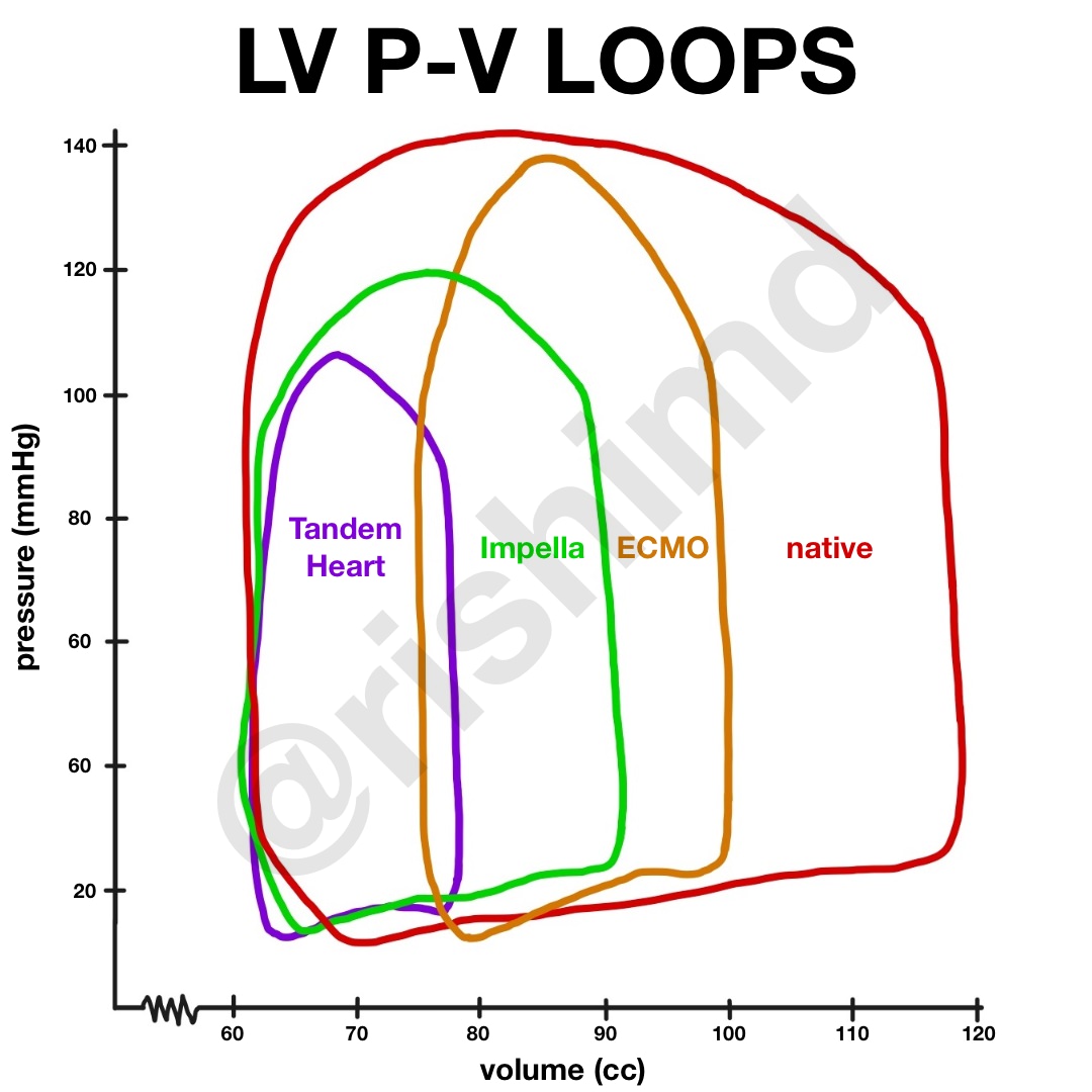
Left Ventricular Pressure Volume Work Loop With Mechanical Circulatory Support Rk Md

Processes Ib Physics Stuff

Numerical And Experimental Analysis Of The Cavitation And Study Of Flow Characteristics In Ball Valve